


Performance Validation in Endotoxin Filtration: The LAL Test and Sampling Guide
June 20, 2026
Producing purified water that meets the required quality parameters is only one part of a safe hemodialysis water system. Once the water leaves the reverse osmosis unit, its microbiological quality must be protected throughout the distribution network until it reaches the dialysis machines. For this reason, dialysis loop line design must be approached as a complete engineering process that includes pipe sizing, circulation flow, pressure control, connection details, sampling points, disinfection compatibility and long-term maintenance access.
A properly designed hemodialysis distribution loop delivers purified water to each dialysis machine connection and returns unused water to the treatment system. Continuous circulation helps reduce stagnant areas, limits water residence time and allows disinfectants or hot water to reach the entire distribution network more effectively. An incorrectly designed line, however, may allow high-quality product water to become recontaminated inside the piping system. It may also contribute to biofilm formation, unstable pressure, excessive dead volume and difficult maintenance procedures.
There is no single standard drawing that can be applied to every dialysis center. The number of treatment stations, simultaneous water consumption, total pipe length, building layout, technical room location, disinfection method, treatment system capacity and possible future expansion must all be evaluated together. A professional dialysis loop line design should therefore be supported by hydraulic calculations, site-specific analysis, commissioning measurements and ongoing microbiological and endotoxin monitoring.
How Does a Loop Line Affect Hemodialysis Water Quality?
A dialysis water circulation line is not simply a passive pipe installed between the water treatment unit and the treatment area. It directly influences water temperature, flow velocity, surface contact, residence time and exposure to potential contamination points. Low flow conditions, unnecessary fittings, blind branches and difficult-to-clean components can create environments in which microorganisms may attach to internal surfaces and begin forming biofilm.
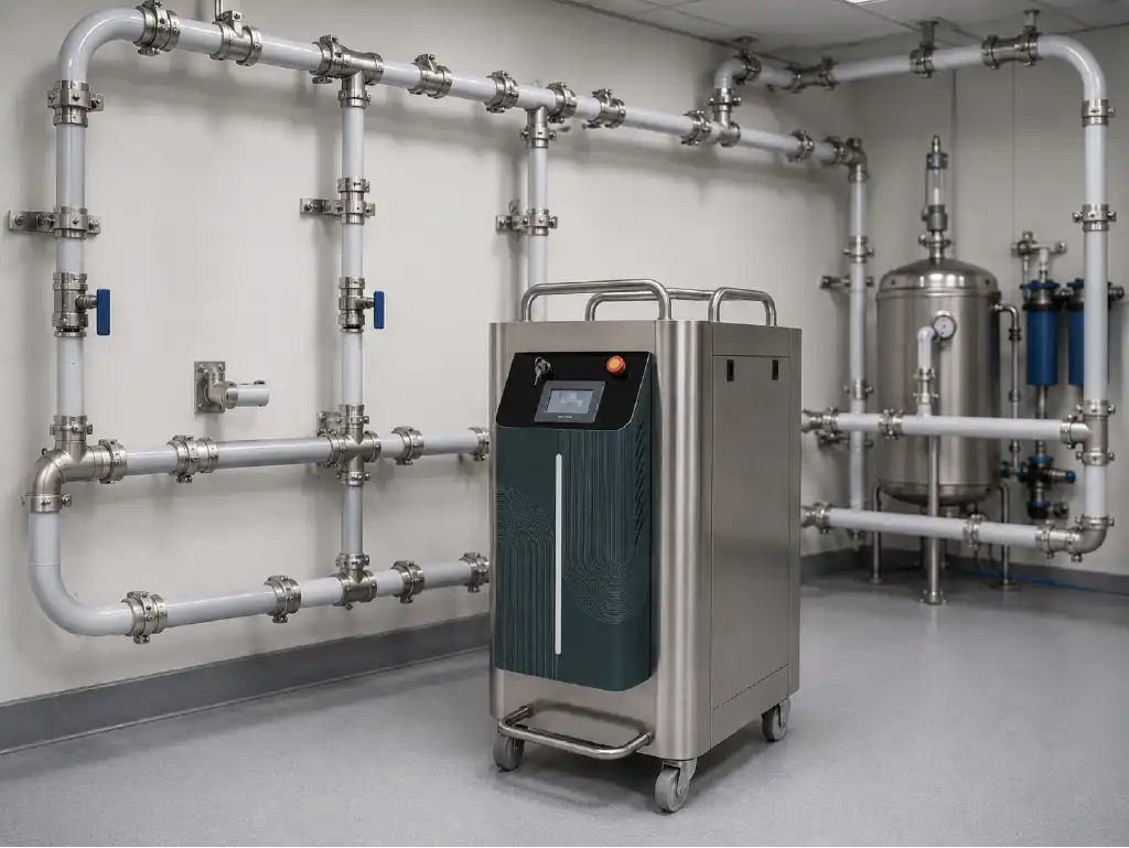
For this reason, dialysis loop line design should be considered an extension of the water treatment process rather than a separate plumbing task. Even when the reverse osmosis unit produces water within the required chemical and microbiological limits, unsuitable distribution conditions can compromise water quality before it reaches the dialysis machine.
The U.S. Centers for Disease Control and Prevention states that hemodialysis patients may be exposed to approximately 300 to 600 liters of water each week. This makes the integrity of the water treatment and distribution system particularly important. The CDC also recommends regular disinfection of dialysis water distribution systems and advises facilities to avoid unused branches, dead ends and unnecessary connections that may harbor microorganisms. Additional information is available in the CDC guidance on water use in dialysis.
The Role of Continuous Circulation in Microbiological Safety
Continuous circulation allows purified water to move through the entire loop and return to the treatment system. This movement helps reduce local stagnation and limits the amount of time water remains stationary inside the pipe. It also supports more consistent distribution of hot water or an approved chemical disinfectant during routine disinfection procedures.
However, the fact that a circulation pump is operating does not automatically mean that every part of the system has adequate flow. The actual return flow at the most distant point must be measured and verified. During periods of peak consumption, when several dialysis machines draw water simultaneously, circulation should still remain within the required operating range.
A well-designed system maintains sufficient flow at the furthest treatment station while also preserving measurable circulation in the return line. If the return flow falls too low during heavy use, certain parts of the system may behave like stagnant branches even though the piping is physically arranged as a loop. Pump performance, pipe diameter, fitting losses, elevation differences and the water consumption profile of the dialysis machines must therefore be evaluated together.
Stagnant Water and Dead Volume Risk
Dead volume can occur in blind-ended pipes, long machine branches, unused valves, oversized connection lines and sections of an old distribution system that are no longer in service. When water movement is limited in these areas, microorganisms may attach to the internal surface and develop into an established biofilm structure.
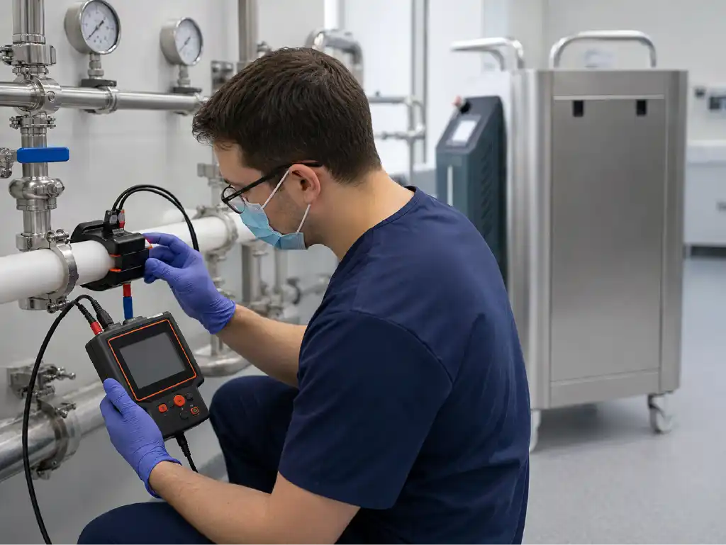
Stagnant water is not only a risk during weekends or extended facility shutdowns. An oversized pipe, a long flexible connection hose or an unnecessary branch may create local low-flow conditions during normal daily operation. These areas may not be adequately exposed to the same flow, temperature or disinfectant concentration as the main loop.
Biofilm can protect microbial colonies from routine disinfection and may cause microorganisms to be released into the water intermittently. Therefore, a single acceptable sample result does not always prove that every part of the distribution line is free from contamination. Safe operation requires a combination of appropriate design, validated disinfection, representative sampling and regular trend analysis. More information about this process can be found in the article on biofilm formation and prevention methods.
| Design Element | Potential Risk | Recommended Engineering Approach |
|---|---|---|
| Oversized pipe diameter | Low flow velocity and increased water residence time | Calculate pipe diameter according to simultaneous demand and minimum return flow |
| Long or unused branch | Dead volume and microbial attachment | Keep branches short and remove unused lines from the main loop |
| Excessive fittings | Surface irregularities, pressure loss and difficult maintenance | Simplify the route and use hygienic connection components |
| Insufficient return flow | Loss of circulation during peak consumption | Verify pump performance, pressure losses and pipe sizing together |
| Poorly positioned sampling valve | Non-representative test results and sampling contamination | Install accessible, short and hygienic sampling points |
How Should the Correct Pipe Material Be Selected?
The pipe material used in a dialysis distribution system should not be selected solely according to initial installation cost. Internal surface quality, connection method, chemical resistance, thermal resistance, pressure class, expected service life, installation quality and maintenance access should all be considered.
The selected material must also be compatible with the disinfection method used by the facility. If the system will be disinfected with hot water, chemical agents or a combined procedure, the pipe, fittings, seals, valves and adapters must remain within the manufacturer’s approved operating limits for temperature, concentration and exposure time.
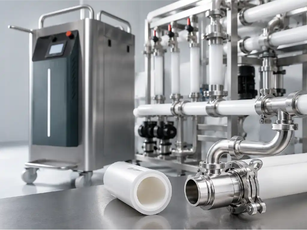
Every component in contact with purified water forms part of the same hygienic chain. A high-quality pipe cannot compensate for poorly designed valves, incompatible seals or fittings that create internal cavities. Material selection should therefore cover the complete assembly rather than the pipe alone.
Hygienic Advantages of PEX-A Pipe Systems
A PEX-A loop line may allow long sections of the distribution network to be installed with fewer mechanical connections. The flexibility of the pipe can reduce the number of elbows and joint components required along complex routes. Fewer connections may help limit potential leakage points, installation irregularities and areas where cleaning or disinfection becomes difficult.
The smooth internal surface of PEX-A piping can also support hygienic operation when combined with appropriate flow conditions. However, no pipe material can completely prevent biofilm formation on its own. Microbiological safety depends on the combined performance of pipe selection, system geometry, circulation, disinfection procedures, water temperature management and periodic verification.
Reeinmer PEX-A piping systems can be evaluated as part of an integrated solution that includes the distribution loop, machine connectors, valves and hygienic fittings. During project planning, parameters such as working pressure, maximum temperature, chemical exposure, bending radius, fixing intervals and approved installation procedures should be reviewed in detail.
Selecting Stainless Steel Connections and Hygienic Fittings
Stainless steel components may be used at dialysis machine connections, sampling valves, equipment transitions, adapters and technical service points. However, the term “stainless steel” alone is not sufficient as a specification. Material grade, surface finish, weld quality, internal geometry, seal compatibility and resistance to the selected disinfection method must also be evaluated.
Fittings that create internal protrusions, cavities or sections that cannot drain properly may increase the risk of dead volume. Full-bore valves and smooth transition fittings should be preferred where technically appropriate. Sudden reductions or expansions in the flow path should be minimized, and every component should remain accessible for inspection and replacement.
Transitions between polymer piping and stainless steel components should be made using manufacturer-approved adapters. After installation, pressure testing, leakage testing, flushing and disinfection validation should be documented. The commissioning process should also confirm that none of the connection points adversely affect circulation or create areas in which disinfectant contact may be insufficient.
Essential Dialysis Loop Line Design Criteria
Dialysis loop line design requires coordination between hydraulic engineering, architectural planning, infection control and equipment operation. The route between the technical room and treatment area should be as short, traceable and serviceable as possible. Pipes should be protected against mechanical damage, uncontrolled heat sources, direct sunlight and unsuitable environmental conditions.
Connections located above suspended ceilings or inside technical shafts should remain accessible. A design that appears clean on an architectural drawing may become difficult to maintain if valves, sampling points or adapters cannot be reached without damaging building finishes or interrupting treatment areas.
Future capacity should also be considered. However, leaving long blind branches for possible future dialysis stations is not an appropriate expansion strategy. Instead, the project should define how future equipment can be connected hygienically without creating unused sections in the existing loop.
Flow, Pressure and Return Line Planning
The flow calculation should begin with the maximum water consumption of all dialysis machines that may operate simultaneously. The required circulation allowance, possible flushing demand and an appropriate design margin should then be added. Pipe diameter must be selected by considering both total flow and pressure losses caused by pipe length, fittings, valves and changes in elevation.
A pipe that is too small may cause excessive pressure loss, unstable machine supply and high flow noise. A pipe that is unnecessarily large may reduce velocity and increase water residence time. Therefore, the objective is not to choose the largest possible pipe but to determine the diameter that maintains suitable operating pressure and continuous return flow under realistic demand conditions.
Pump selection should not focus only on producing high pressure at the beginning of the loop. The system must maintain the required pressure at the furthest dialysis station while preserving adequate flow in the return line. During commissioning, flow and pressure measurements should be taken at the supply, middle, furthest and return sections of the system.
If balancing valves or pressure-control components are required, they should be cleanable, compatible with disinfection and designed without unnecessary internal cavities. Their settings should be recorded and protected against uncontrolled adjustment.
The connection point of the return line depends on the overall treatment system architecture. Tank-based and direct-feed systems may require different arrangements for return water, temperature control, UV treatment, final filtration and disinfection circulation. These details should be determined through project-specific engineering rather than copied from a generic installation.
Within Reeinmer Hemodialysis Water Treatment Systems, the treatment unit and distribution loop are evaluated as a single water quality system. This approach helps ensure that product water quality, hydraulic performance, automation and disinfection remain compatible throughout the complete installation.
Sampling Points and Service Accessibility
Sampling points should be positioned so that microbiological and endotoxin test results accurately represent the performance of the complete distribution system. Typical locations may include the product water outlet, loop supply, representative treatment stations, the most distant point and the return line. The final number and location of sampling points should be determined according to the size of the facility, risk assessment, applicable standards and the water quality monitoring plan.
A sampling point should not be created using a long blind pipe or a conventional faucet that is difficult to disinfect. The connection should be short, accessible, easy to clean and capable of providing controlled water flow. The sampling procedure should define valve disinfection, flushing time, sterile container handling, transport conditions and laboratory analysis methods.
Improper sampling technique may produce a contaminated result even when the distribution system is operating correctly. For this reason, sampling procedures should be standardized and performed by trained personnel. Results should be evaluated as trends rather than isolated values.
Service access is another important factor that is often overlooked during initial installation. Pumps, sensors, valves, sampling points and machine adapters should be accessible without requiring unnecessary interruption of dialysis operations. Critical components should be clearly identified, the direction of flow should be documented and the as-built piping diagram should be kept up to date.
The hemodialysis water treatment system operation and maintenance guidance can support the development of structured daily, monthly and periodic inspection procedures.
Expert note: Passing a pressure test alone is not sufficient to confirm that a dialysis distribution loop is ready for clinical operation. The commissioning file should include hydraulic measurements, disinfection validation, microbiological and endotoxin test results, material documentation, the final piping diagram and clearly assigned maintenance responsibilities.
Practical Recommendations for Reducing Biofilm Risk
Biofilm risk should not be managed only by attempting to remove established contamination after it appears. The main objective should be to create system conditions that make microbial attachment and biofilm development more difficult from the beginning.
Effective dialysis loop line design, high-quality installation, continuous circulation, suitable disinfection and routine water analysis should be managed under a single quality plan. When these elements are treated separately, recurring microbiological problems may continue even after individual components are replaced.
Designing a System Without Dead Ends
A loop without dead ends should maintain continuous circulation and keep machine connection branches as short as possible. Unused outlets should not remain on the system as long capped branches. If a dialysis station is permanently removed, the unused line should be hygienically disconnected from the main loop rather than simply closed at its end.
The number of elbows, tees, valves and reducers should be limited to those required for safe operation and maintenance. Unnecessary bends or additional fittings installed only for routing convenience may increase pressure loss and create irregular internal flow conditions.
After installation, the line should be inspected for drainage, low points, trapped water and possible air pockets. Air accumulation may interfere with circulation, affect disinfection contact and create unstable measurement results. Drain points should also be designed carefully so that they do not become new blind branches when they are not in use.
Every wetted component should remain within the normal circulation and disinfection path. A component that is isolated from regular flow may become a contamination reservoir even when the rest of the loop is operating correctly.
Disinfection Compatibility and Maintenance Planning
The disinfection method should be selected during the design phase rather than after the loop has been installed. If hot water, chemical disinfection or a combined method will be used, the temperature, concentration and contact-time limits of the pipe, fittings, seals, sensors and machine connections should be verified in advance.
The automation system should support the selected disinfection procedure by monitoring relevant operating parameters. Depending on the system, these may include return temperature, circulation time, chemical concentration or rinse completion. Appropriate safety controls should prevent the system from returning to clinical use until disinfection and rinsing have been completed and verified.
The CDC recommends regular disinfection of dialysis water distribution systems and microbiological testing at least monthly. However, the final schedule should also consider current standards, local regulations, manufacturer recommendations, facility risk assessment and historical test trends.
Facilities should not rely only on fixed calendar intervals. Changes in microbiological counts, endotoxin values, pressure, temperature or return flow should be reviewed over time. A gradual increase toward an action level may indicate a developing system problem even before a formal limit is exceeded.
- Record loop supply and return flow at defined intervals.
- Compare pressure, temperature and conductivity trends.
- Clean and sample each monitoring point according to a documented procedure.
- Do not leave unused machine connections attached to the active loop.
- Verify rinsing and residual chemical levels after disinfection.
- Perform root-cause analysis when results are unsuitable instead of replacing components without investigation.
If microbiological or endotoxin results increase repeatedly, the problem should not automatically be attributed to the reverse osmosis unit. Storage tanks, UV units, final filters, loop surfaces, sampling methods, machine connections and disinfection distribution should all be investigated.
Where appropriate, endotoxin filtration solutions may be integrated into the treatment system. However, additional filtration should not be used as a substitute for identifying hydraulic or microbiological problems within the distribution loop.
Frequently Asked Questions
Why are dialysis water distribution lines designed as loops?
A loop configuration allows unused purified water to return to the treatment system and supports continuous circulation throughout the distribution line. This helps reduce stagnant water and dead-ended sections. However, the physical loop shape alone is not sufficient. Return flow, pressure losses and disinfection circulation must also be verified through measurements.
Does a PEX-A loop line completely prevent biofilm?
No. The smooth internal surface of PEX-A and the ability to install it with fewer fittings may help reduce biofilm risk, but no material can eliminate the risk by itself. Continuous circulation, suitable disinfection, hygienic design and regular microbiological monitoring are still required.
What is the ideal pipe diameter for a dialysis loop?
There is no universal pipe diameter suitable for every dialysis center. The correct size depends on the number of machines operating simultaneously, water consumption, total line length, fitting losses, pump performance and the required return flow. The diameter should be determined through a project-specific hydraulic calculation.
Where should sampling points be installed in a dialysis loop?
Common locations include the product water outlet, the beginning of the loop, representative treatment stations, the furthest point and the return line. The exact arrangement should be based on facility size, risk assessment and the water quality monitoring plan. Sampling valves should be short, hygienic, accessible and easy to disinfect.
How often should a dialysis loop be disinfected?
The frequency should be determined according to the system design, disinfection method, manufacturer instructions, applicable standards, local requirements and water analysis results. Regular disinfection and at least monthly microbiological monitoring are commonly recommended, but facilities may require more frequent action depending on risk and result trends.
Can an existing dialysis loop be improved without complete replacement?
In some systems, improvements can be made by correcting pump performance, removing unused branches, replacing unsuitable fittings, improving sampling points or revising the disinfection procedure. However, widespread biofilm, incompatible materials, inaccessible connections or serious hydraulic imbalance may require partial or complete reconstruction. The decision should be based on site inspection and analytical results.
Professional Dialysis Loop Engineering with Reeinmer
A safe hemodialysis water infrastructure cannot be achieved by evaluating the water treatment unit and the distribution network as separate systems. Reeinmer Hemodialysis Water Treatment Systems provides project-based support for existing system analysis, capacity calculations, pipe and fitting selection, hydraulic planning, sampling point positioning, disinfection strategy and commissioning verification.
For new dialysis centers or facilities experiencing recurring microbiological problems, a site-specific dialysis loop line design can be developed according to treatment capacity, building conditions and operational requirements. The engineering team evaluates not only visible installation issues but also the hydraulic and microbiological causes behind repeated deviations in water quality results. To request a technical assessment, site survey, project consultation or quotation, visit Reeinmer Hemodialysis Water Treatment Systems. Correct engineering, documented commissioning, regular validation and sustainable technical support help protect dialysis water quality throughout the operational life of the system.