
A completed disinfection cycle does not, by itself, prove that a hemodialysis water distribution loop is ready for clinical use. With heat, the required temperature must reach the relevant parts of the circuit and remain there for the specified contact period. With a chemical agent, the required concentration must circulate through the defined system, followed by effective rinsing and a suitable residual test. Readers searching for hemodialysis RO membrane CIP should also recognize that membrane cleaning and loop disinfection are separate activities with different acceptance evidence.
Verification must reflect the facility’s actual piping, points of use, equipment instructions and selected disinfectant. A “cycle complete” indication on a controller is useful operational information, but it cannot replace review of supply and return measurements, remote point checks, event records and applicable water quality results. The process becomes especially important when a center has experienced repeated microbiological excursions or unexplained variation between sampling locations.
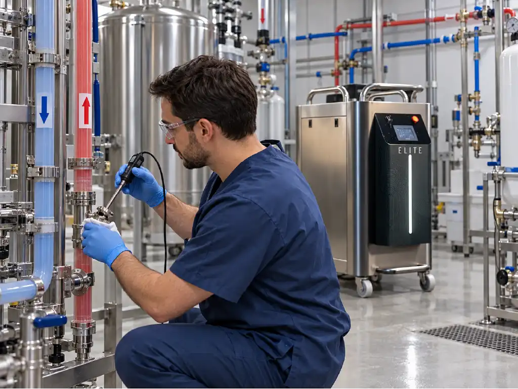
Start with an approved procedure that identifies the treatment boundary, critical points, instruments, acceptance criteria and people authorized to release the system. The Reinmeer guide to dialysis loop line design explains why flow, branches, sampling points and the return path must be considered together. These design details directly influence whether a disinfection process reaches the water contact surfaces it is intended to treat.
How Is Thermal Disinfection Performance Checked?
For a thermal cycle, the essential question is whether the specified water contact surfaces receive the required temperature for the required time. Reaching a setpoint at the heater outlet is not proof of equivalent conditions at the last outlet or in a poorly circulating branch. Pipe length, insulation, pump operation and valve positions can all affect what happens beyond the equipment room.
The applicable temperature and holding period should come from the validated system procedure and the instructions for its components. Materials exposed to heat, including pipe, seals, tanks and connected devices, must be suitable for the intended cycle. A convenient temperature figure taken from another installation should not be treated as a universal acceptance criterion for a different dialysis center.
Monitoring supply and return temperatures and the most remote point of use
The supply sensor shows the conditions delivered to the distribution line. The return sensor shows what reaches the end of the circulating path. Their combined records help identify heat loss and a slow warm-up. Even a satisfactory return reading, however, cannot prove that every side branch has warmed adequately. A closed valve or a low-flow connection may remain outside the effective treatment path.
The most remote point of use is often a sensible verification location because it lies far along the water path. Distance alone is not enough to select every critical location. Different floors, seldom-used connections, long branches and changes in pipe diameter may create other challenging points. A facility-specific hydraulic review should identify which outlets require direct checks and which permanent sensors provide representative data.
Where the design permits, compare an installed sensor with an appropriately calibrated independent thermometer at a defined sample port. Record the instrument identity, measurement location and time. A temperature measured on the outer pipe surface is not necessarily the temperature of flowing water inside it; the procedure must state which measurement is used for acceptance and how it is obtained safely.
If a remote point reaches the target late, counting contact time from heater start can overstate the period of effective treatment. The approved cycle should define when the hold period begins and what happens if a critical reading drops below its acceptance condition. A persistent difference between supply and return warrants investigation of circulation, insulation, valve settings or the distribution layout.
Contact time, temperature records and the cycle report
A useful report contains a time history, not merely a highest recorded temperature. The trace should make warm-up, hold and cool-down phases distinguishable. Recording intervals need to be suitable for identifying meaningful interruptions. If the data are too sparse, a brief drop in temperature may disappear between readings while the final report still appears satisfactory.
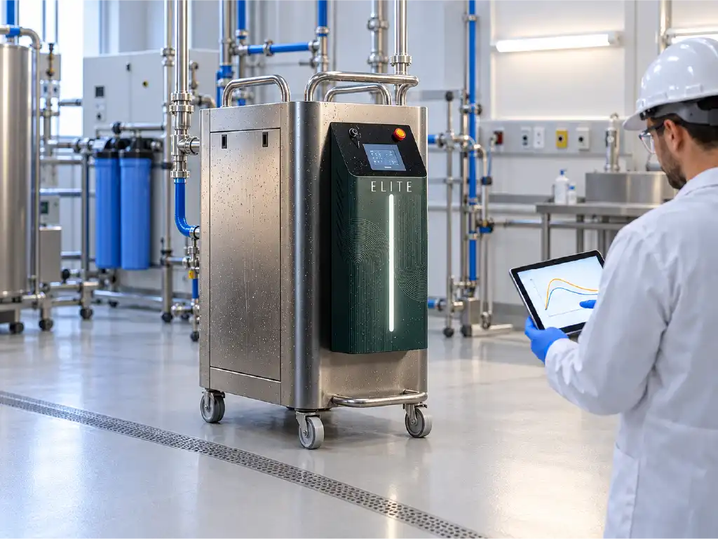
The report should identify the system, cycle date, sensor locations, set procedure and responsible operator. Record alarms, power interruptions, pump stops and manual overrides as well. An automated success message does not resolve a documented deviation; the approved procedure must determine whether a cycle can be accepted, requires an additional review or must be repeated.
A simple verification matrix helps the team review the same evidence each time. Numerical limits should be established in the facility procedure using the relevant equipment instructions and quality requirements before the cycle begins.
| Check | Evidence to retain | Initial deviation review |
|---|---|---|
| Supply and return | Time-stamped temperature trend | Flow and heat loss |
| Critical outlet | Location and on-site reading | Branch and valve condition |
| Contact period | Time after required conditions are met | Cycle repeat decision |
| Cycle events | Alarms and interventions | Root cause review |
Thermal cycle records should also be considered alongside scheduled microbiological and endotoxin monitoring. They answer related but different questions: the cycle trace documents process conditions, while water testing helps evaluate the ongoing quality of water at selected points. The CDC guidance on water use in dialysis recommends regular disinfection of distribution systems and dialysis-specific microbiological testing. Applicable local requirements and current standards must also be followed.
Expert note: When an outlet repeatedly returns an adverse test result, increasing the heater setting without investigation may miss the cause. Review sampling technique, return flow, unused branches and areas where biofilm may persist. Confirm material compatibility before changing a thermal cycle, and document any revised setting through the facility’s change control process.
How Is Safety Verified After Chemical Disinfection?
Chemical disinfection requires proof of two distinct conditions. During treatment, the selected agent must reach the defined surfaces at an appropriate concentration for the required exposure period. Before clinical use, rinsing and testing must show that the agent has been removed to the applicable acceptance level. A valid dosing record does not establish that the post-rinse water is ready for treatment.
Agent selection should account for the compatibility of the loop pipe, seals, tank, filters and connected equipment. Concentration, temperature where relevant, and contact time should follow the product and system manufacturers’ instructions. The process boundary matters as well: a loop disinfectant should not be allowed to enter an RO membrane or another incompatible component simply because it belongs to the same overall water system. CDC guidance states that products used to disinfect dialysis systems should follow manufacturers’ recommendations.
Concentration, contact time and circulation through the entire loop
A correct concentration in the preparation vessel does not prove that the same condition exists at the far end of the loop. Take measurements at the procedure’s designated supply, return and critical use locations. The test method must be suitable for the chosen chemical, with its measuring range, expiration date and limitations checked before use. Results should be recorded with their exact sample locations.
Contact time should not automatically start when dosing begins. The procedure should define its start in relation to the verified arrival of the required concentration at critical points and the agent manufacturer’s instructions. If concentration falls during circulation, an acceptable initial sample cannot validate the whole exposure period. Investigate dilution, chemical consumption, mixing and circulation before deciding whether to repeat the treatment.
Closed valves, bypasses and unused branches can prevent the solution from reaching part of the network. Compare the current piping drawing with actual valve positions before the cycle. Define whether the tank, return connection and individual use points are included. Where outlets must be opened, specify the sequence, safe handling method and waste route so that disinfectant cannot inadvertently enter a clinical connection.
Seeing the pump run is not sufficient evidence of full-loop circulation. Review return flow, system pressure and measurements at representative outlets together. An unexpectedly weak result in one branch may point to a stagnant section, partial blockage or hydraulic imbalance. If the same location fails repeatedly, a design correction may be more effective than repeating an otherwise unchanged chemical cycle.
Rinsing, residual testing and the return-to-service decision
Once the defined exposure period is complete, remove the agent using the approved rinse procedure and suitable water. Do not assume that a familiar rinse duration fits every installation. Loop volume, tank connections, branch geometry, chemical behavior and actual flow paths affect how quickly the system clears. A clean sample near the treatment unit does not establish that a remote outlet has also cleared.
Use a residual test appropriate to the disinfectant and interpret it against the approved acceptance criterion and the test’s detection capability. Record the sample point, time, method and result. Check the points identified in the facility procedure, which may include the return line and selected outlets. If a strip is expired, a reading is uncertain or the instrument is outside calibration, repeat the check with suitable materials before release.
A satisfactory chemical residual result does not replace microbiological or endotoxin testing. Where prior results indicate contamination or suspected biofilm, follow the approved resampling and corrective action plan. The sample method, transport conditions, any required neutralization and laboratory reporting time all affect the usefulness of subsequent results. The related endotoxin filtration validation guide describes how sampling locations help distinguish problems in treatment equipment from those in the loop.
Release to clinical service should be a documented decision by the people assigned that responsibility. Review the cycle trace, chemical preparation record, contact period, final rinse and residual findings together. If any required evidence is missing or unacceptable, keep the affected water path out of use, repeat the relevant step under the procedure and investigate the cause. CDC guidance emphasizes thorough rinsing and residual testing after certain chemical disinfection processes used in dialysis equipment.
How Does Hemodialysis RO Membrane CIP Differ From Loop Disinfection?
Hemodialysis RO membrane CIP is a separate cleaning process intended to address deposits or fouling affecting a reverse osmosis membrane, subject to the membrane and equipment manufacturers’ instructions. Loop disinfection targets microbiological control in the defined distribution circuit. The processes may occur within the same facility, but they have different flow boundaries, chemical compatibility requirements, performance measures and release checks.
Do not order RO membrane chemical cleaning on the basis of one isolated conductivity reading. Review normalized product flow, pressure differential, rejection performance, feed water characteristics and pretreatment history together. An apparent membrane performance loss may reflect fouling, but instrument error, seal leakage or operating conditions can produce other patterns. The guide to elevated dialysis RO outlet conductivity provides a useful framework for investigating those differences.
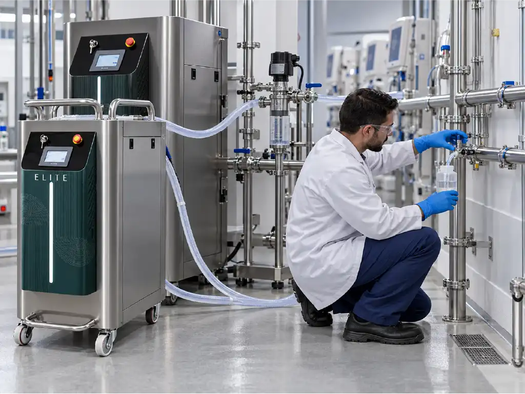
After dialysis RO cleaning, the team assesses the membrane’s return to its defined operating conditions with appropriate performance measurements. After loop disinfection, the evidence instead centers on temperature or chemical exposure, residual removal and relevant water quality checks. Keeping these records distinct prevents a successful maintenance step in one part of the system from being mistaken for proof that another part is ready for patient care.
Frequently Asked Questions
Is return-line temperature alone enough to verify heat disinfection?
No. It is an important indicator of conditions at the end of the circulating path, but an isolated branch or closed connection may behave differently. Review supply and return data with measurements at the critical points selected by the facility’s risk assessment. Their locations and acceptance criteria should be defined before the cycle starts.
When does the thermal contact period begin?
It begins according to the validated cycle definition for the particular system. In practice, the important issue is whether the procedure’s critical locations have reached the required conditions, rather than whether the heater has merely switched on. Use time-stamped records to confirm the actual start and any subsequent temperature interruption.
Is one chemical residual sample enough after rinsing?
Not necessarily. Sampling locations should reflect how the agent circulated and how rinse water leaves the network. A remote branch may clear differently from the return line. Use a chemical-specific test at the locations required by the approved procedure, and repeat ambiguous results before making a release decision.
Does a negative residual test prove that dialysis water is microbiologically acceptable?
No. The residual test addresses removal of the specified disinfectant. Bacterial and endotoxin conditions require separate assessment. Following a previous excursion, repeat sampling and review the results under the facility’s corrective action and return-to-service procedures rather than relying on the residual result alone.
Can RO membrane CIP and loop disinfection share a single cycle?
That cannot be assumed. Feasibility depends on the installed design, isolation arrangements, chemical compatibility and manufacturers’ instructions. Each activity needs a defined purpose, flow boundary, rinse sequence and acceptance checks. An unintended chemical path could damage a membrane or reach a clinical water connection.
Build a verification plan around your actual facility. Reviewing loop disinfection involves more than checking a controller setting. Pipe routing, return flow, remote use points, instruments, sample ports and previous laboratory results all help establish whether a cycle is effective and properly documented. Reinmeer Su Arıtma Sistemleri can support a site-specific technical review of existing hemodialysis water treatment infrastructure and help identify practical monitoring or design improvements.
If RO output has also declined, the need for hemodialysis RO membrane CIP can be assessed separately using membrane performance and pretreatment data. Whether you are planning a new center, investigating recurring water quality deviations or seeking a clearer validation record, explore Reinmeer hemodialysis water treatment solutions to request technical information, a site survey or a project-based quotation.
Sharing your current piping diagram, recent cycle reports and water analyses will help the engineering discussion begin with evidence. The aim is a traceable process suited to your equipment, approved procedures and operating conditions.
The images are for illustrative purposes and were created using artificial intelligence.